o.css">
Arduino 1541 Interface
Updated : 03/11/2023
The interface itself :
After a bit of mucking around with a logic analyzer and reading some fantastic documentation referring to the Commodore IEC serial protocol Iv'e managed to construct an interface using an Arduino Uno that I think should allow for the Commodore 1541 or similar disk drive to connect with any computer running any operating system that can use the Arduino's serial USB connection.
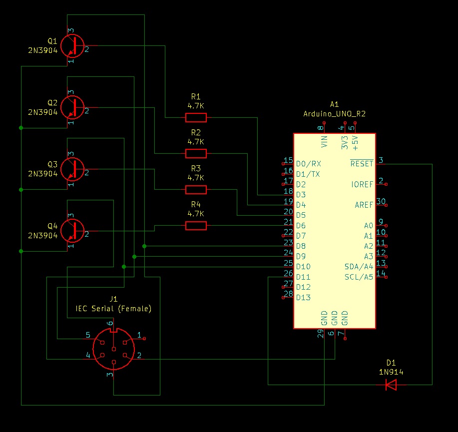
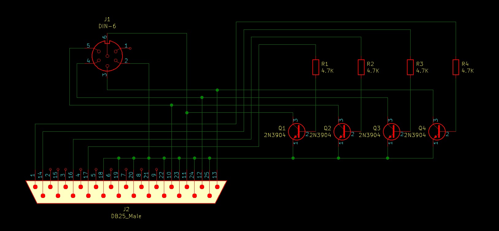
The interface also requires a XA-1541 cable (easily obtainable off eBay etc) or a simple shield can be made using four NPN switching transistors, four resistors and a diode. A schematics can be found below. The normal schematic calls for BSV52 transistors but I believe most NPN transistors should work fine.
So far the interface has only been tested on standard 35 track disks so compatibility with other formats is unknown. The Windows software provided (Sorry, not yet avaliable as it's become a little out of control) is written for 35 track disks but can be easily modified. Although the interface allows for any sector to be read individually (Useful for creating D64 images) it also uses the drives DOS system to allow for single files to be read in their entirety. (Useful for creating PRG files)
The interface using the drives DOS system also allows for files such as .prg files to be saved to disks and commands to be sent to the drive to format disk's or scratch files off a disk etc... The only thing I haven't managed to get working so far is to be able to write entire sectors, something that would be useful for writing D64 images to disk. I get some sort of systax error when writing the data to the drives internal buffer, a work in progress...
While the software (both Window's and Arduino code) seem to work fine they are still in a very early development stage and I have no doubt are still riddled with buggs so please use at your own risk as I hold no responsibility for any hardware/software damage or loss.
How is it used :
Anyway, enough of that. So how is it used?
The interface simply uses the arduino's usb to communicate at a buad rate of 115200 so could essentially be used by any serial terminal, the program provided for use in Windows or you can write your own program to use it in your preferred operating system. it's commands use a singular lower case letter to instruct the interface on what command to execute followed by any required information for said command such as file name, track and sector number etc... The command is executed by sending the 'carage return' character. 'chr(13)'
A list of it's commands are as follows :
'l' for load file. eg 'lMY FILE' will start streaming the contents of the file name 'MY FILE'.
's' for save file. Save file is a bit more complicated so i will cover this later.
'r' reads a sector. eg 'r0105' will start streaming the contents of track 1, sector 5.
'w' write a sector. Not working yet...
'c' sends a command. eg 'cN0:MY DISK,69' will format a disk with the name 'MY DISK' and the ID of 69.
'f' tells the drive you are finished after reading a sector.
'm' sets the soft interleave and retry count. More on this later.
'n' sets the latch value. More on this later.
'e' reads the drives error channel and streams it back.
'o' tells the drive to reset.
'i' set's the ID of the drive you want to comunicate with. eg i08 for drive 8, i10 for dirve 10
When the interface streams back data from the disk or channel it comes back as an eight bit hex value consisting of two numbers/letters and a space. The end of the file/sector or channel is indicated by a 'XX' whith no space.
Saving a file :
Saving a file happens in two stages :
Stage 1 is where you instruct the interface to save a file and give it the filename. eg 'sMY FILE'
Stage 2 is a bit fome complex. Once the filename is created or the last byte of data has been written the interface will reply with an 'x', when this happens it is upto the PC etc to send a byte of data (in HEX format) to the interface for the drive to write.
The data needs to be sent with a leading character and a terminating character. In this case all data except for the last byte sould be sent with a lower case 'x' for the leading character and a 'y' as the terminating. The final byte is sent with a 'z' as the leading character.
Examples would be 'xA6y' to send the HEX vaue of A6 to be written and 'zA6y' for the final byte. The Carage Return character is not required for this data transmission.
Interleave, retrys and latch :
This is not a funtion as of yet as it's locked to the defaults but it will allow you to change the drives interleave, how many times it will retry something and the latch value. Not exactly sure what the latch value is yet but Star Commander seems to set it so we'll find out in time.
My Windows program :
(Sorry, not yet avaliable as it's become a little out of control)
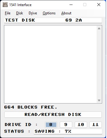
The Windows program is a quick program that I put together that allows for most if not all functions of the interface. It allows you to :
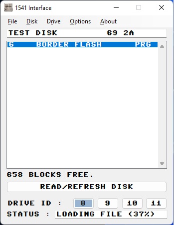
Read the directory of the disk.
Read a program from the disk and save it, a 'PRG' file for example.
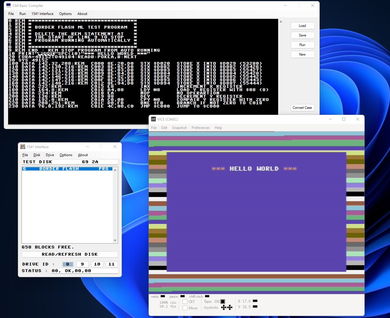
Read a program from the disk and run it through an emulator.
Save a file (PRG for example) to the disk.
Create a D64 file of the disk.
Format the disk.
Scratch (delete) a file off the disk.
Hopefully soon write a D64 file to the disk.
The program is a quick throw together so no doubt needs a lot of refining.
If you have any questions etc about this project, any project on this site or any ideas about any future projects feel free to pop by on my Discord server, say hi and fire away. Copy the following link text into your browser to join my Discord server : "https://discord.gg/SzFh5j3sw5"
Screenshots :

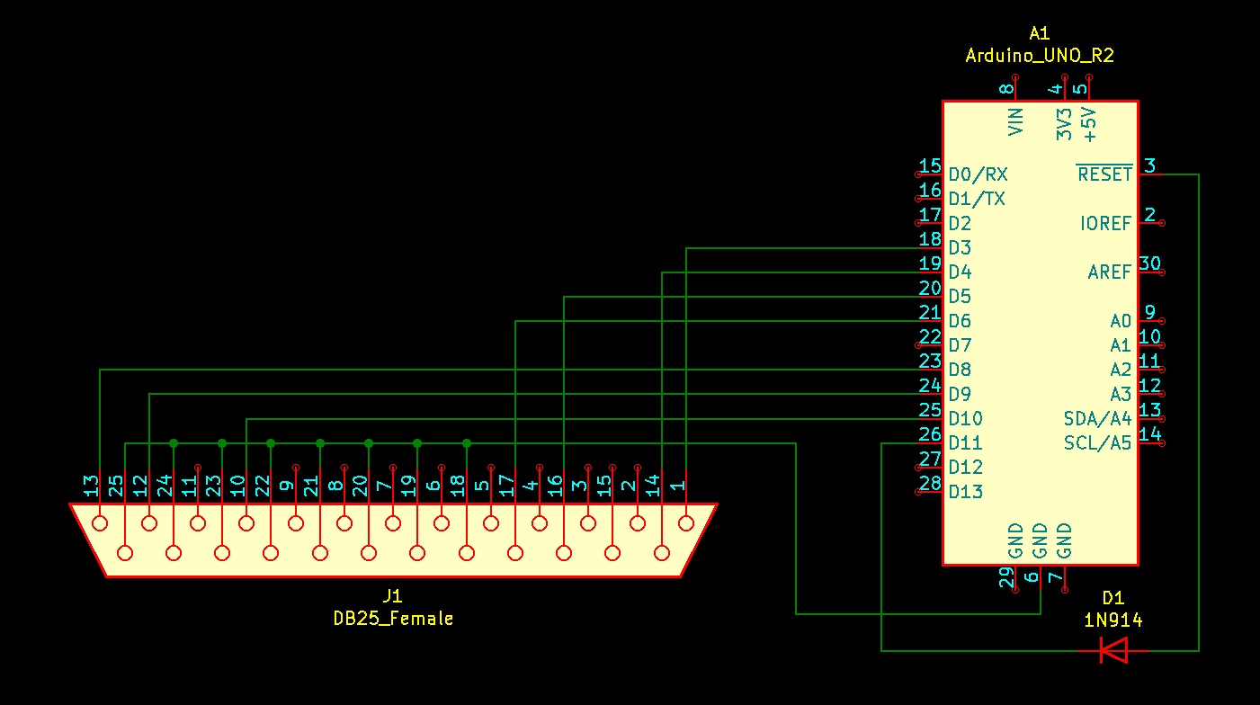
Schematics :
Below are the schematics for wiring the Arduino straight to Commodore IEC connector, the wiring for Arduino to a DB25 connector when using a XA-1541 cable and the wiring for the XA-1541 cable. (Note: I chose the 2N3904 transistors as these are readily avaliable from my local electrionics supplier and they work fine but I believe most NPN transistors should work fine.)
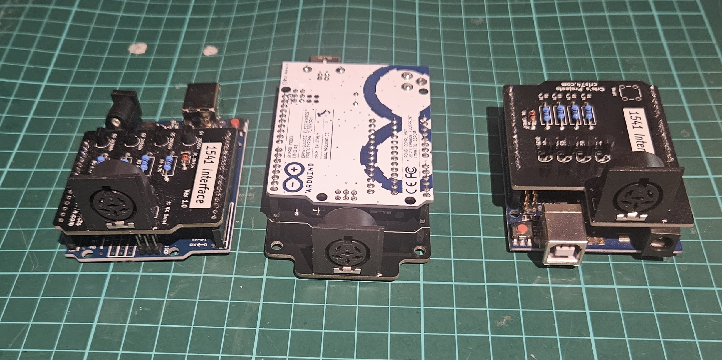
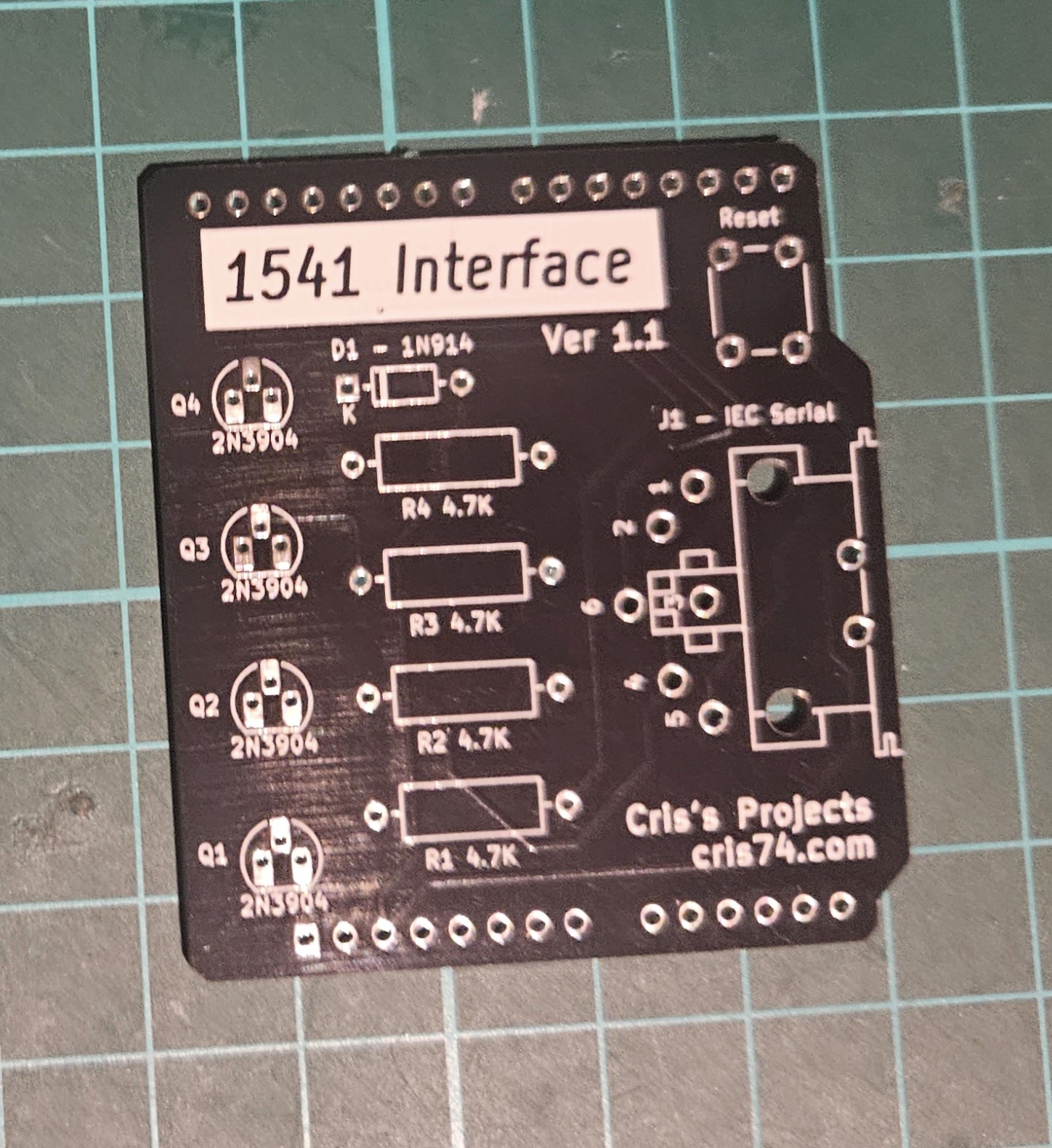
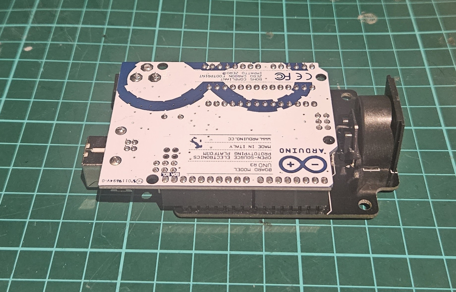
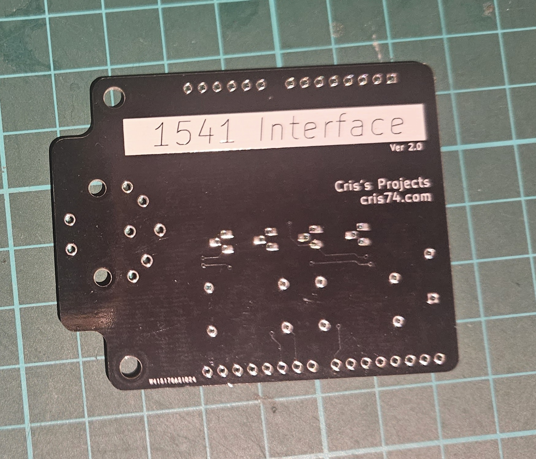
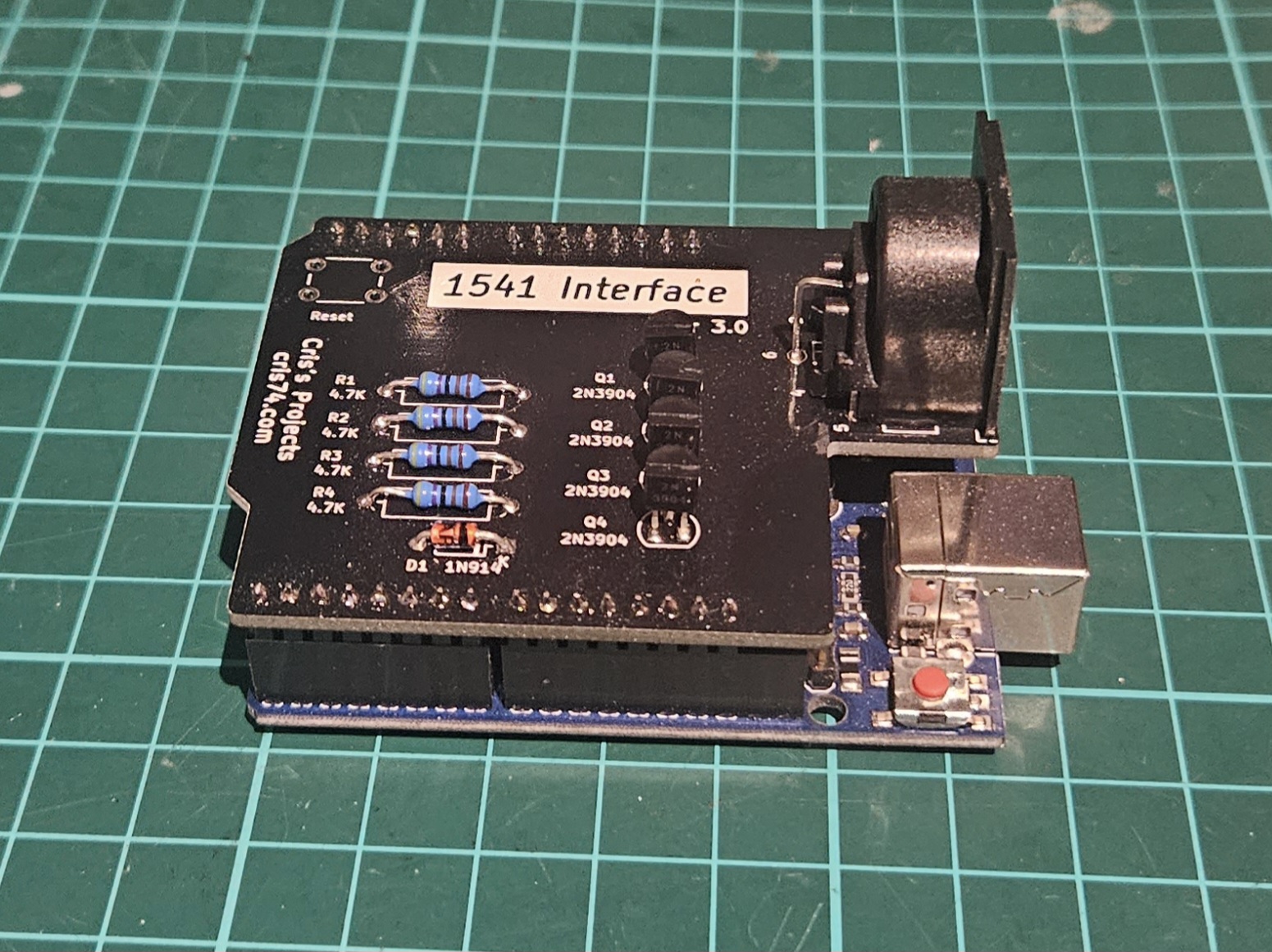
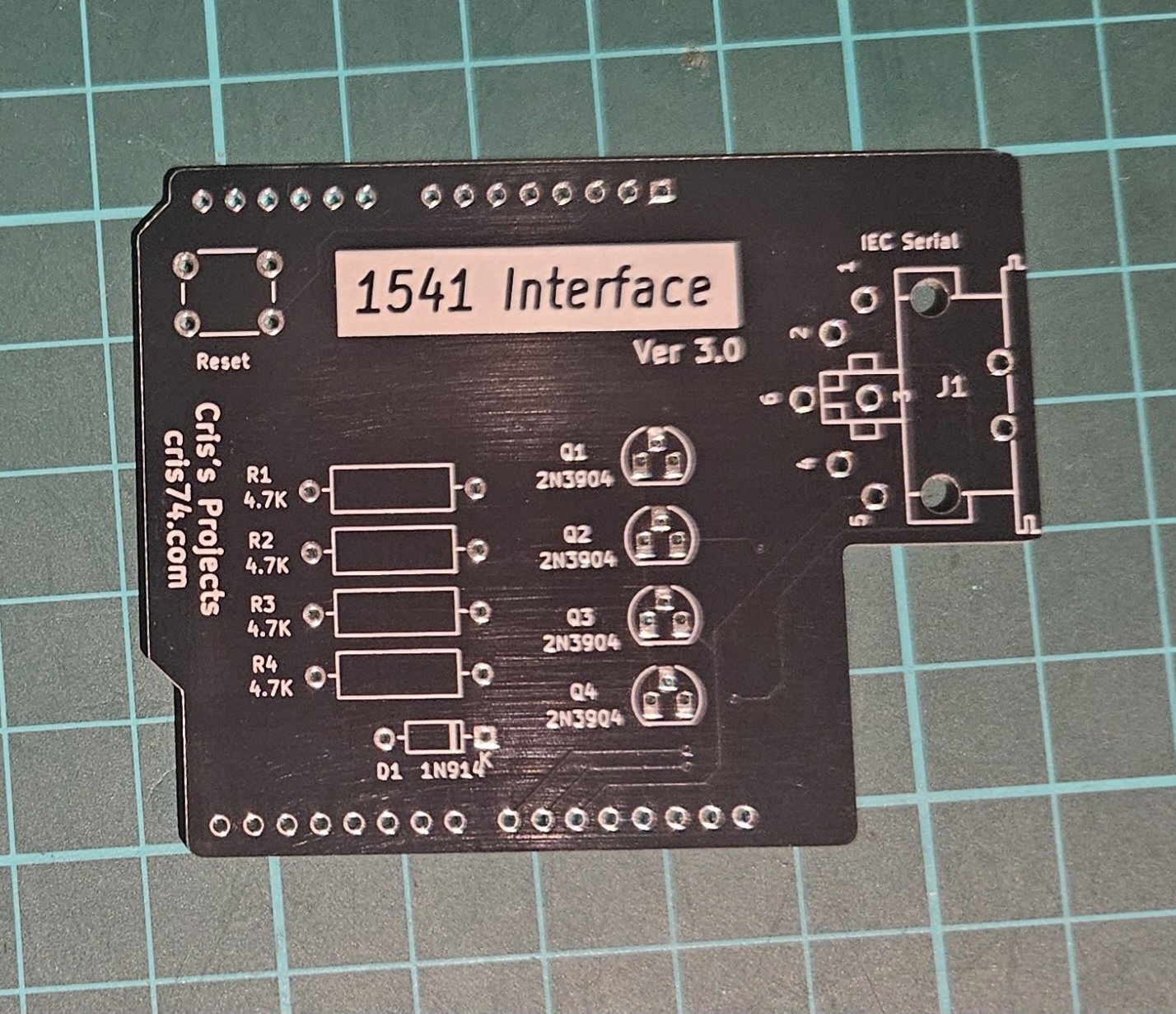
Arduino Shields :
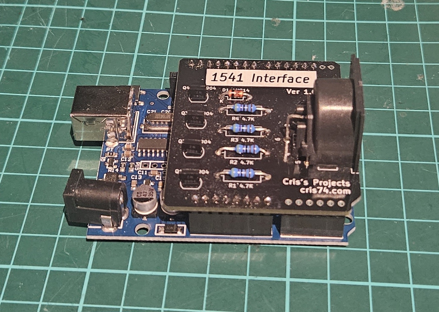
After having a bit of a play with KiCad I've managed to create three different styles of Arduino Shields for use with the 1541 Interface.
For me I prefer V2 as although it's longer it is more compact and easier to 3D print a case for.
Most of the components standard transistors, resistors and diodes but the DIN connector is a HIRSCHMANN MAB 6 H (https://au.element14.com/hirschmann/mab-6-h/socket-din-pcb-6pin/dp/809901)
The PCB gerber files are downloadable below.
V1
V2
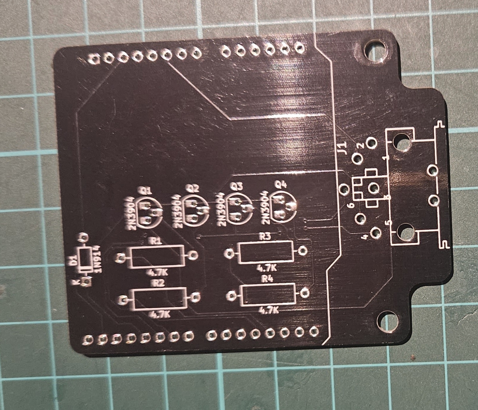
V3
Downloads :